Howto: Build a Cheap, Modular Off-camera dSLR eTTL Flash Extension
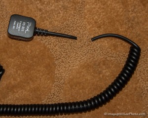
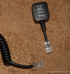
 I was going to help shoot my aunt and uncle’s 50th anniversary event. I didn’t really know what would be going on and I thought it might be an opportunity to augment ambient light via a my eTTL flash. I have a 2 ft. long, stretchy off-camera cable Pixel eTTL Off-Camera Shoe Cord
 (a $20+ replacement for the $65+ Canon OC-E3 “Off Camera Shoe Cord 3”
). But 2–3ft away from the camera was not interesting, so I thought I would do a little hacking to make it easy to move the flash as far away as I would like. Here’s a little “hotel-room hackery” on how I turned my short extension into a modular long extension. The same hack can be applied to a similar Nikon 4765 SC-28 TTL 9-ft. Remote
(or compatible) cord.
Off-camera flash is one of the easiest ways to improve the lighting in a shooting situation. The coiled cord may extend to as far at 9 or 10 ft. but you’d be playing tug-o-war with the flash, and that may still not be far enough away. I decided to cut the cable and add some connectors so that I could use it at its current length or longer cables to extended it as far away as I’d like. I chose to use readily available computer networking connectors and cables to make this hack possible. Also, another of my uncles had the tools and connectors I could use to do the job in my hotel room.
Uh, well, when I arrived and got the crimp tool from him (which allows me to attach the connectors to the cable), I found that it did not have wire cutters and strippers that other crimp tools have. So, I got some scissors (easily found) and cut the cable on the side where the connector slides onto the camera’s hotshoe. I cut it mid-way between the coils and the connector to give enough room to make a mistake on either side.
In retrospect, I should have cut the cable closer to the coils so that it would leave a longer end to allow more flex when a heavy cable is attached.
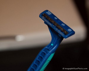
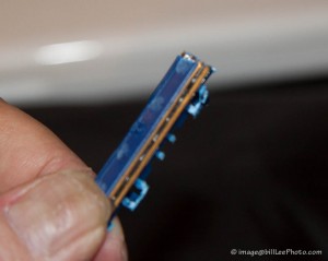
Stripping the rubbery outer insulation was more problematic (the scissors weren’t sharp enough to “cut the mustard”). Hm! Well, I had an old disposable, “safety” razor laying around (the hotel room), so I used the scissors to chop the safety parts away.
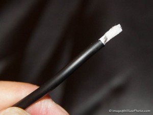
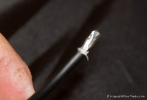
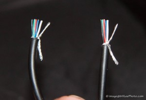
The razor blade was exposed just enough for me to score the outer sheath and break it off— about 3/8″. After tearing off the sheath, I found paper wrapped around fine, stranded wires, surrounding 5 solid-core wires. This represents the 6-connections found on the Canon Speedlite hotshoe mount. I needed to twist the fine strands into a single twisted wire—twisting all of them made the result too thick; so I pared away enough of the strands so that the twisted result would just barely fit into the connector. I cut off the remaining strands. I did this for both cut cable ends.
I tested the length of the exposed wires by sliding them into an RJ-45, Ethernet connector to make sure that the wires could slide all the way to the end—cutting back the insulation sheath enough to allow the wires to reach the end without binding. I had to leave enough insulation to be crimped by the end of the connector—the wires should not be exposed beyond the opening of the connector.
Now, the important part. I flattened and arranged the wires in exactly the same order (left to right) counting the twisted strands as one wire. It didn’t really matter what the order was so long as they matched for both exposed ends. I tried to find a “natural” order, where a majority of the wires fell into place (by squeezing the cable ends flat) matched between the two ends; then I adjust any misordered wires until their order matched. (Be sure to check and recheck the ordering).
Then, I fit them carefully into the slots of the connector. Since there were only 6-wires and the connector accepts 8, I kept an empty slot on either side of the 6, being careful that the stranded “wire” fit cleanly into its slot. After inserting both ends of the cables into their respective connectors, I, again, checked the wiring order for both ends.
Finally, I held the wires deep into the end of the connector and seated the connector solidly into the crimp tool. Closing the tool onto the connector caused it to bind the wires and crimp the insulator in place. After rechecking the other end’s wire order inside the second connector, I crimped it tightly. I finished the construction!
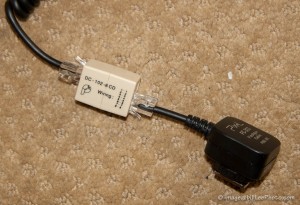
Now, I use a straight, female-female “inline-coupler” to connect those ends to use as before. With a second adapter, I can add an Ethernet cable of any length to extend my flash as far away as that cable will allow.
These Ethernet cable connectors may not be the most compact nor visually appealing, but they are cheap and readily available. It is easy to find 20′, 50′, 1000′ cables at an electronics or office supply store, in a pinch—though I do not know whether the signalling will work at 1000′ length.
Quick List Instructions
So, after making you read through all that, here are the brief instructions.
Parts:
- 2 RJ-45 ethernet connector
- 2 (1 required, 1 optional) ethernet (8P8C) (straight-through) inline coupler; aka female-female straight-through connector
- 1 RJ-45 crimp tool (preferably with built-in wire cutter and stripper)
- 1 Off-camera hotshoe extension cable
- 1 (optional) long ethernet cable
- Cut your precious hotshoe extension cable
- Strip insulation from ends of both sides of cable (appx 3/8″; test fit into connectors—see above)
- Twist stranded wires into a single “wire” (omit enough strands to allow it to fit into an RJ-45 wire slot)
- Order wires to match (very, very important!)
- For each cable end, insert the 6-wires into an RJ-45 connector, careful that the two empty slots also match.
- Crimp the connector onto each cable end.
- Reconnect with an inline coupler or use 2 couplers and a long ethernet cable to put the flash far away.
Alternate Solution
Here’s a link to someone else’s approach, including a video at cheesycam.com/diy-ettl-flash-cable-extension


